Thursday, 19 December 2013

From old-school solder to Bigshot fever: our year on Twitter

It is only when you look back over your Twitter timeline that you realise a) that was the crazy year that was, and b) how we ever survived without the excitement of a mention, a reply or an RT. From old school solder to super-fast service, these are some of our favourite posts of 2013.
Our customers like to order like its 1999.

Obviously we take great pride in our delivery times, but even we seemed to have surpassed ourselves in receiving, picking and despatching an order from Colchester to deepest North Wales in around 15 hours. All this at a time when much of the country was blanketed in snow. Go us!

I like to think of the above as our alternative corporate biography.

We were delighted to sponsor and follow the progress of a Walsall school's weather balloon project. The unseasonable wintry weather (see above) put paid to their planned Spring launch, but they could not have picked a more glorious day to finally make their ascent in the summer. It was exciting to plot the balloon's journey via tweets and a GPS tracking service on the day, and even better when we saw the incredible footage the camera took 20 miles above the Earth. Queen Mary's Grammar School are now planning to go even higher in 2014 with their 'Beat Felix' (Baumgartner, who skydived from 24 miles up) project.


Thankfully solder doesn't seem to have a sell-by date!

In October we launched our mobile website, putting an end to all that tapping and enlarging ...


In late summer we stumbled across news of the Bigshot - the world's first DIY digital camera. It had been developed specifically for education, giving children an insight into how the electronics of photography works. We loved the concept, and were delighted to become the first (and at present only) UK distributor of the product. A lovely review by Rachel Riley on The Gadget Show helped the Bigshot buzz, and there will be plenty of cameras under Christmas trees in a few days time.  

 It seems Argos have a rival for their "laminated book of dreams". 

What does 2014 have in store? Follow us on Twitter to find out (but then you probably do already ...)

Friday, 6 December 2013

The War on Warehouse Costs

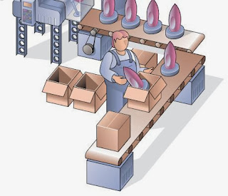
What is the most frustrating aspect of the distribution business? Among ours at Rapid, in no particular order, are picking errors highlighted by customers; delays to customer orders; waiting for stock to arrive that does sell, and having your warehouse cluttered with stock that doesn't.

Almost 40 per cent of UK companies with stockholding operations rank stock level optimisation high on their priorities, according to a survey of warehouse operators carried out for leading WMS provider Access Delta. 

The accompanying whitepaper, Space and stock: the financial frontier', suggests many businesses without a WMS are missing out on a relatively easy route to reduced cost and improved service. The survey of around 130 warehouse and distribution managers highlighted the challenges facing businesses, such as the issue of waste, the popularity of Pick and Pack functionality, optimising stock levels and space usage.

This infographic summarises the key facts of the survey.


The key finding highlights that business maturity may have a large part to play. Larger, more established businesses tend to have established and robust processes from point of order to point of despatch: with these in place, stock level optimisation in relation to order and volume patterns is an obvious next step, with clear benefits for cash flow amongst other criteria. Smaller and newer businesses are often more focused on the need to grow the business and meet every customer demand, in the hope of repeat business and an enhanced service reputation.

The whitepaper highlights that small businesses are particularly vulnerable to short term cash-flow problems, and sub-optimal stocking levels, with insufficient stock in some lines leading to lost sales, while too much working capital is tied up in slow-moving lines - providing a very sound recipe for cooking up a cash flow crisis.


With stock levels optimised, it becomes possible to think rationally about optimising space utilisation. The survey finds that three quarters of respondents are not doing it very well or efficiently, demonstrating there is enormous room for improvement. Warehousing space is not cheap, and the apparent need to increase storage area can be a real brake on company growth.

Rob Hodgson, supply chain divisional sales manager for Access Group, commented, "Companies who optimise their stock levels often 'discover' significant volumes of stock that they didn't know they had available. When this has been cleaned up they may find they no longer need to expand their warehousing space. And this can mean a serious cost saving."

"The survey and respective whitepaper highlights that regardless of size, companies need to go far beyond their current thinking to discover the benefits of optimised stock and warehouse space", continues Rob. "A WMS that can integrate financial visibility and other key functions across the operation will bring greater benefits both to cash flow and customer service."

This post has been produced with the assistance of Access Delta, a provider of Warehouse Management Solutions. 

Tuesday, 12 November 2013

Bare Conductive - creativity with the popular Touch


Does crowdsourcing actually work?


The creative types at Bare Conductive would answer with a resounding "yes!". 

A couple of weeks ago they launched their latest project, an interactive prototyping platform called Touch Board. They hoped to raise pledges worth £15,000 on the creative fundraising website Kickstarter, to enable the London-based company the chance to put the board into production. Within a few days, however, their target had been reached. The money continued to flood in and at the time of writing they had raised over £60,000, with two weeks of the funding period still to run – giving Bare Conductive the opportunity to invest in other areas. 


What does their success prove? That the right product, marketed well, will always find willing investors.  It also shows that this small Spitalfields start-up, founded by four Royal College of Art graduates in 2010, have a knack for developing products with the popular touch. 

At the heart of all Bare Conductive products is the unique electric paint – a material which was born not in a lab, but online. None of Bare’s co-founders Matt Johnson, Isabel Lizardi, Bibi Nelson and Becky Pilditch are chemists by background and incredibly did much of their research and development on Wikipedia. It is all the more remarkable then that what they were able to create. 


A kind of user-friendly, heat-free solder, this ingenious substance can simply be drawn onto paper or card like liquid wire, creating simple circuits between components like batteries, resistors and LEDs.
Children, crafters and hobbyists with no soldering experience can use conductive paint to create 2 or 3-D projects with basic electronic effects. Bare have produced a range of kits catering mainly for the schools market, enabling kids to make flashing greetings cards or illuminated model houses.  

The key to the company’s success so far has been the versatility and extreme usability of conductive paint. The way it has been embraced by the design, engineering and artistic community, and played its part in countless projects, works and installations, can be seen on the Bare Conductive Community page. Some hobbyists and model railway enthusiasts even prefer it to solder. And it is the way the team are adapting the technology and taking it into different areas that is currently so exciting about Bare Conductive. 


So what will you be able to do with the Touch Board? What won’t you be able to do with it! 

The paint can be used as a sensor or a switch, linked to the board so that particular sounds or effects can be created whenever you touch the painted area. Simply by connecting a battery, a speaker and an SD card to the Arduino-compatible device, you could bring sounds to your children’s book, create audio in your art project, play instruments you have painted, draw a light switch or a security system. As with most Internet of Things projects, the only real limits are your own imagination. 

As Matt Johnson says: "Devices no longer have to look high tech to be high tech. Our goal is to put interactivity onto objects you don't expect."

A range of Bare Conductive products are are available at Rapid, including the seasonal Merry Resistivities kit.  

Tuesday, 29 October 2013

Developing creativity

Bigshot camera shows kids science behind photography


There has been plenty of buzz about the Bigshot camera recently – and this exciting educational product, which has been compared to the Raspberry Pi for the potential it could have to engage young hands and minds with technology, is now available to pre-order in the UK exclusively from Rapid. 

Bigshot is a kit form digital camera aimed at children aged 8 and above which provides a complete learning and creative experience. As with the Raspberry Pi, hobbyists and project makers have also cast seductive eyes towards the camera.

The camera is assembled from a 43-piece kit

The primary function of Bigshot is to give an insight into the science and engineering behind photography. As children assemble the camera from the 43-piece kit, they learn about optics, mechanics, electromagnetism, electronics and image processing. Once built, Bigshot is a fully functioning 3 megapixel sensor digital camera, with viewfinder, flash, timer and settings wheel – as well as a hand crank to provide back-up power. Images can be framed in regular, panoramic and stereo views – with the latter providing 3D photographs. This will give children a unique opportunity to document the world around them. 


 Bigshot is supported with extensive online resources, which teachers can use to prepare lessons, after-school activities, weekend and holiday projects. With Bigshot as their tool, teachers are encouraged to produce STEAM education – STEM with added Arts.

The creator of Bigshot, Shree Nayar, was inspired to create the product when he saw the documentary film Born into Brothels. The film chronicled how children in one of the poorest parts of Kolkata were given cameras to photograph the world around them. Prof Nayar, who heads up the Computer Vision Laboratory at Columbia University, trialled the product with pupils in the US, India, Japan and Vietnam and with the profits from the sales hopes to be able to donate the product to children in the developing world. “In an age when software rules I want kids to know how to build hardware”, says Nayar. “We describe concepts that children would normally encounter at college, but try to make them accessible even to an eight or 10-year old.”


"Unlike a camera that you can snap together and you don't have to worry about the parts inside, in this case each component that the kid is handling has to be safe and be something that reveals a concept."

We are so excited that Bigshot can be pre-ordered now from Rapid, the exclusive distributor of Bigshot in the UK.

Monday, 28 October 2013

Boxes of fun!


Friday, 18 October 2013

Rapid goes mobile!


We know how frustrating it is to access the right website, at the right time, but at the wrong size. All that tapping and enlarging eventually saps your soul.

That is why we have launched a mobile version of our website – m.rapidonline.com – which makes searching, browsing and buying from Rapid on your smartphone or tablet so much easier.
 
This is what some of you have been saying on Twitter:


Tell us what you think of the mobile site - so that we can continue to improve it. 

Wednesday, 2 October 2013

The Velleman K8200 - the Big Build!


Chris Calver
The Velleman K8200 is the most affordable 3D printer on the market. Part of the deal, however, is that you must assemble it first. But how long does it take? What skills do you need? More importantly, how many cups of tea do you need? Rapid's Education manager Chris Calver (right) built it and explains what buyers should expect before they can start printing.

When I received my K8200 3D printer, the first thing that occurred to me was how small the box was. Then you open the box and realise just how many parts there are!

Thankfully, Velleman have packaged all the parts in smaller bags containing just a handful of pieces. Each of these bags is referred to in the instructions as you progress through the build which makes it nice and easy to find the right parts and keep track of what you have used.

Let the build begin!
I used the online instructions for building my kit but you can download and print a PDF if you find it easier. The instructions have plenty of pictures in and the text is easy to follow.

Velleman ease you into the build gently by getting you to build the support for the filament spool first. Once this is done it is on to the serious business of the X-axis carriage which involves fixing the linear bearings into their clamps. These are retained with fairly large circlips which need a pair of circlip pliers to apply them without launching them across the room. If you don’t have any, beg, borrow or buy a cheap pair which are available for about £4. Y axis is then fitted on top of the X-axis, again using circlips to fix the linear bearings.

The next step involves adding the first stepper motor and drive belt to move the Y axis. The belt is cut from a continuous length so be sure to count the correct number of teeth. The belt is then fixed to the bottom of the Y-axis by means of a plastic clamp. Care needs to be taken when tightening this to avoid cracking the plastic. Luckily for me, Velleman included a couple of spares in the kit!

The first stage of the build is concluded by adding a limit switch which the printer will later use when setting it’s datum points before each print. Once this is fitted, you’ll be left with a really nice looking piece of hardware for which you are likely to reward yourself with a nice cup of tea.

The completed X-axis carriage
The next phase is to build the printer’s base. This is constructed from 4 lengths of aluminium extrusion which is fixed together using some ingenious 90 degree clamps with captive fixings. You simply slide them into the extrusion and tighten the allen bolts. There are a number of square nuts that also need to be inserted during assembly of the base which will be used to secure other pieces to the frame later. Finally, the X-Y assembly is added and your printer is starting to take shape.

The printer's base
Now it’s time for the Z-axis. Again, this is built using aluminium extrusions and the clever 90 degree clamps. The Z-carriage is then added which uses more linear bearings and circlips. The horizontal bar which will eventually carry the extruder is then fitted. The Z-axis is controlled by a threaded rod which runs up the left hand side of the printer. It is attached to a stepper motor at the base and is retained in a bearing at the top. Personally I would like to have seen a sealed bearing used here, because in the workshop environment I can see this open bearing accumulating dirt and becoming an area for regular cleaning/maintenance.

At this point, you will have something that pretty much resembles a 3D printer. Make yourself another cup of tea though, you are only a quarter of the way through the build!


The drive train and extruder body


The next stage is the last part of the drive train and involves adding the stepper motor and drive belt for the X-axis. Again I have a little grumble in that open bearings are used in the belt tensioner which will need cleaning occasionally. The same high quality stepper motor is used on this axis as on the pulley and belts and are nice heavy duty items. The belt itself clamps to the X-carriage using aluminium clamps which feels much better than the plastic item on the Y-axis.

Only a couple of mechanical bits to go now - the main one being the extruder body which will feed the plastic into the ‘hotend’, the part which actually melts and dispenses the plastic. This part of the build only concerns itself with the feed mechanism with the hotend being one of the last things to go on.

The feed mechanism is operated by a stepper motor which drives a special “hob bolt” via two plastic gears. This hob bolt has splines cut in to the thread and it is these splines that will ultimately pull the element into the hotend. The plastic gears seem well moulded and are really tough.  The rest of the body of the extruder is more high quality CNC aluminium which sandwiches a plastic housing. Part of this plastic housing forms a spring loaded tensioner which keeps the filament in place. Again, my only criticism is the open bearing…

The extruder housing

The extruder housing is then mounted to the rest of the frame via some captive nuts in the aluminium extrusion of the Z-Axis. 

Assembling the heated bed 


The K8200 has a heated bed which prevents the plastic warping as it cools and is said to allow higher quality prints. This heated bed is like a PCB with an element running throughout it. The bed is mounted to an aluminium carrier with an insulating layer in between to prevent the heat sinking through the frame of the printer. There is a slightly fiddly moment here when a surface mount NTC thermistor needs to be soldered to the bottom of the bed. This thermistor will allow the control board to keep the bed at the right temperature so it is vital that it is correctly installed. A pair of tweezers makes this task a bit easier!

The NTC Thermistor

The rest of the bed assembly consists of adding some thumb screws which will allow the extruder to be calibrated later in the assembly.


There are three microswitches, one on each axis which allow the printer to detect when it has reached the end of its travel. The controller uses these to set datum points before each print so that it knows the exact position of the extruder in relation to the bed. These are vital to the calibration of the printer and ultimately to the accuracy of the printer. As a result, I was a little disappointed to see that the switch on the Z-axis is only retained by one bolt, meaning that despite the toothed washer behind it, it is too easy for this switch to be knocked out of alignment. My preference would have been for this switch to be mounted through two holes and I will be making my own bracket to make this possible.

Attaching the switch to the Z-axis

The controller board for the printer is the heart of the machine and will control all the stepper motors, limit switches and heaters. It also handles all communications to your PC via a USB interface. The PCB is supplied ready assembled so it is just a case of bolting it to the mounts on the side of the printer. 

It looks a little exposed, but one of the first jobs for your printer will be to print a case to protect the board. What a neat little idea. Velleman supply you with a CAD model for the case so this can be used to calibrate and test the printer!

The controller board assembled to the frame

The wiring loom 


The next task is a big one and is the one that probably requires the most care as well as being the most time consuming – assembling the wiring loom. You are presented with a length of ribbon cable and a whole bunch of ‘Molex’ style connectors. Thankfully, these are at least prewired and stripped but there is still a lot of work to do here.


As with the whole of the build, the instructions are very clear and there are loads of pictures to help you on your way. Each core in the ribbon cable needs to be carefully stripped and tinned, then each needs to be carefully soldered and protected with heatshrink tubing. Remember to put your heatshrink on before soldering the wires as these can’t be added afterwards! 

If you have soldering experience, you will find this job quite easy and you may prefer to assemble the loom off the printer rather than on it as the instructions suggest. For these with less soldering experience, it is worth following the instructions to the letter and taking your time. Errors made here would take a long time to fault find later so check, check and check again.


The final part of the assembly is the hotend which consists of a copper nozzle which runs through a heater block. Another fiddly part coming up - there is a tiny glass bead thermistor which needs to be mounted in a small hole in the heater block. Again, it is crucial to the operation of the printer as this will be responsible for the regulation of the temperature of the heater so it is worth taking your time to make sure you get this bit right. 

The heater block with thermistor fitted


The assembled hotend


Once the hotend is bolted on to the extruder, the heater element and thermistor of the hotend need to be soldered in to the wiring loom. You can now stand back and admire your work; the build is complete!

Mission accomplished


All in all, this took me the best part of seven hours and copious cups of tea. However, if you have some basic soldering and circuit assembly skills it's still fairly straightforward and quite satisfying to build. I hope to blog again soon about the calibration, set-up and software, but this will do for now. If you've got this far with the build you've more than earned yourself one of these:


Remember, the K8200 is available from Rapid for under £700.